


Promoting a healthy environment for your seals
At Flowserve, we recognize that the most effective way to achieve long, uninterrupted mechanical seal life is to create a healthy environment around the seal faces. Piping plans help keep mechanical seals running cool and clean, promote safe handling of dangerous fluids, and extend the operational availability of rotating equipment. Your Flowserve sales engineer can help you identify the right solution for your application.
Single Seals
Plan 01
Internal recirculation is from a high-pressure region of the pump to the seal chamber.
What
Internal seal chamber flush from pump discharge.
Operates similar to Plan 11.
Why
Seal chamber heat removal.
Seal chamber venting on horizontal pumps.
Reduce risk of freezing/polymerizing fluid in exposed Plan 11 piping.
Where
Custom seal chamber, most likely an ANSI/ASME pump.
Clean, moderate temperature fluids.
Used with single seals, rarely with dual seals.
Preventative Maintenance
Flush typically cannot be directed over seal faces and seal heat removal is limited.
Calculate flush flow rate based on head loss through internal porting.
Plan 02
Dead-ended seal chamber with no recirculation of flushed fluid.
What
Dead-ended seal chamber with no flush.
Why
No fluid recirculation needed.
Where
Cooling jacket seal chambers in high-temperature services.
Clean fluids.
Top-entry mixers/agitators with dry seals.
Heating jacket seal chambers in fluids that solidify at low temperatures.
Preventative Maintenance
Process must have adequate boiling point margin to avoid vaporization.
Cooling fluid in seal chamber jacket may be needed at all times in hot services.
Horizontal equipment must be self-venting.
Often used in combination with steam quench, Plan 62.
Plan 03
Circulation between the seal chamber and the pump created by the design of the seal chamber.
What
Circulation created by the design of the seal chamber.
Why
No external fluid recirculation needed.
Solids removal from seal chamber.
Where
Large bore/open throat seal chambers.
Dirty or contaminated fluids.
Preventative Maintenance
Proper seal chamber design helps prevent solids from collecting at the seal faces.
Plan 11
Recirculation of high-pressure product to seal.
What
Seal flush from pump discharge through orifice.
Default single-seal flush plan.
Why
Seal chamber heat removal.
Seal chamber venting on horizontal pumps.
Increase seal chamber pressure and fluid vapor margin.
Where
General applications with clean fluids.
Clean, non-polymerizing fluids.
Preventative Maintenance
Use an orifice with a minimum 3 mm (0.125 in.) diameter.
Calculate flow rates to size orifice for adequate seal chamber flow.
Increase boiling point margin with proper orifice and throat bushing sizing.
Flush should be directed over seal faces with piping at 12 o’clock position.
Typical failure mode is a clogged orifice. Check temperatures at pipe ends.
Related Products
Orifice/Throttle Bushing
Plan 13
Recirculation from the seal chamber through a flow control orifice and back to the pump suction.
What
Recirculation from seal chamber to pump suction through orifice.
Standard flush plan on vertical pumps.
Why
Continuous seal chamber venting on vertical pumps.
Seal chamber heat removal.
Where
Vertical pumps.
Seal chamber pressure is greater than suction pressure.
Moderate temperature fluids with moderate solids.
Non-polymerizing fluids.
Preventative Maintenance
Vent piping loop prior to starting vertical pumps.
Use an orifice with a minimum 3 mm (0.125 in.) diameter.
Calculate flow rates to size orifice for adequate seal chamber flow.
Reduce seal chamber pressure with proper orifice and throat bushing sizing.
Typical failure mode is a clogged orifice. Check temperatures at pipe ends.
Related Products
Orifice/Throttle Bushing
Plan 14
Recirculation from pump discharge through a flow control orifice to the seal and simultaneously from the seal chamber through an orifice.
What
Seal flush from pump discharge and recirculation to pump suction with orifices.
Combination of Plan 11 and Plan 13.
Why
Continuous seal chamber venting on vertical pumps.
Seal chamber heat removal.
Increase seal chamber pressure and fluid vapor margin.
Where
Vertical pumps.
Clean, non-polymerizing fluids at moderate temperatures.
Preventative Maintenance
Use an orifice with a minimum 3 mm (0.125 in.) diameter.
Calculate flow rates to size orifice for adequate seal chamber flow.
Increase boiling point margin with proper orifice and throat bushing sizing.
Flush should be directed over seal faces.
Vent piping loop prior to starting vertical pumps.
Typical failure mode is a clogged orifice. Check temperatures at pipe ends.
Plan 21
Recirculation from a high-pressure region of the pump through a flow control orifice and cooler, then into the seal chamber.
What
Seal flush from pump discharge through orifice and cooler.
Cooler added to Plan 11 flush increases heat removal.
Why
Seal cooling.
Reduce fluid temperature to increase fluid vapor margin.
Reduce coking.
Where
High-temperature service, typically less than 177°C (350°F).
Hot water over 80°C (180°F).
Clean, non-polymerizing fluids.
Preventative Maintenance
Seal cooler and piping must have air vents at highest elevation. Vent before starting.
When using 682 Seal Cooler, pipe with series flow to maximize heat transfer.
Use an orifice with a minimum 3 mm (0.125 in.) diameter.
Calculate flow rates to size orifice for adequate seal chamber flow.
Increase boiling point margin with proper orifice and throat bushing sizing.
Regularly monitor cooler inlet and outlet temperatures for signs of clogging or fouling.
Related Products
Orifice/Throttle Bushing
NX Seal Coolers
682L Seal Cooler
682M Seal Cooler
682H Seal Cooler
A625 Seal Cooler
ANC Seal Cooler
AFC Seal Cooler
Plan 23
Recirculation from a circulation device in the seal chamber through a cooler and back into the seal chamber.
What
Seal flush from internal pumping device through cooler.
Standard flush plan in hot water services.
Why
Efficient seal cooling with low cooler duty.
Increase fluid vapor margin.
Improve water lubricity.
Where
High-temperature service, hot hydrocarbons.
Boiler feed water and hot water over 80°C (180°F).
Clean, non-polymerizing fluids.
Preventative Maintenance
Seal cooler and piping must have air vents at highest elevation. Vent before starting.
When using 682 Seal Cooler, pipe with parallel flow to minimize head loss.
Seal chamber requires close clearance throat bushing to isolate process fluid.
Tangential seal gland taps should enter at bottom and exit at top.
Regularly monitor cooler inlet and outlet temperatures for signs of clogging or fouling.
Process fluids with iron should flow through magnetic separator before cooler.
Related Products
Orifice/Throttle Bushing
NX Seal Coolers
682L Seal Cooler
682M Seal Cooler
682H Seal Cooler
A625 Seal Cooler
ANC Seal Cooler
AFC Seal Cooler
Magnetic Separator
Plan 31
Recirculation from a high-pressure region of the pump through a cyclone separator delivering the clean fluid to the seal chamber.
What
Seal flush from pump discharge through cyclone separator.
Centrifuged solids are returned to pump suction.
Why
Seal chamber heat removal.
Solids removal from flush and seal chamber.
Where
Dirty or contaminated fluids, water with sand or pipe slag.
Non-polymerizing fluids.
Preventative Maintenance
Cyclone separator works best on solids with a specific gravity twice the process fluid.
Seal chamber pressure must be nearly equal to suction pressure for proper flows.
Piping should not include an orifice and is not expected to vent the seal chamber.
Typical failure mode is clogged separator or pipes. Check temperatures at pipe ends.
Related Products
Plan 32
Flush is injected from an external source into the seal chamber.
What
Seal flush from an external clean source.
Why
Seal chamber heat removal.
Process and solids removal from seal chamber.
Increase seal chamber pressure and fluid vapor margin.
Where
Dirty or contaminated fluids, paper pulp.
High-temperature service.
Polymerizing and/or oxidizing fluids.
Preventative Maintenance
Use throat bushing sized to hold pressure or maintain flow velocity.
To restrict dirty process fluid, regulate injection flow rate.
To increase fluid vapor margin, regulate injection pressure.
Injection fluid must be compatible with process fluid.
Regularly monitor control system for closed valves or signs of plugging.
Related Products
Plan 41
Recirculation from a high-pressure region of the pump through a cyclone separator delivering the clean fluid to a cooler and then to the seal chamber.
What
Seal flush from pump discharge through cyclone separator and cooler.
Combination of Plan 21 and Plan 31.
Why
Seal cooling.
Solids removal from flush and seal chamber.
Where
High-temperature service, typically less than 177°C (350°F).
Dirty or contaminated fluids, water with sand or pipe slag.
Non-polymerizing fluids.
Preventative Maintenance
Seal cooler and piping must have air vents at highest elevation. Vent before starting.
When using 682 Seal Cooler, pipe with series flow to maximize heat transfer.
Cyclone separator works best on solids with a specific gravity twice the process fluid.
Seal chamber pressure must be nearly equal to suction pressure for proper flows.
Typical failure mode is clogged separator or pipes. Check temperatures at pipe ends.
Related Products
Dual Seals
Plan 52
External reservoir providing buffer liquid for the outer seal of an arrangement 2 seal.
What
Unpressurized buffer fluid circulation through reservoir.
Fluid is circulated by a pumping ring in the dual seal assembly.
Why
Outboard seal acts as a safety backup to the primary seal.
Zero to very low process emissions.
No process contamination is allowed.
Where
Used with dual unpressurized seals.
High vapor pressure fluids, light hydrocarbons.
Hazardous/toxic fluids.
Heat transfer fluids.
Preventative Maintenance
Piping loop must self-vent to vapor recovery/flare system near atmospheric pressure.
Process vapor pressure is generally greater than reservoir pressure.
Buffer fluid must be compatible with process leakage.
Primary seal leakage is indicated by increased vent pressure.
Reservoir level indicator shows outboard seal leakage.
Related Products
NR Reservoirs
API 682 Reservoir
DuraClear Barrier/Buffer Fluid
Refill Cart Series
Plan 53A
Pressurized external barrier fluid reservoir supplying clean fluid to the barrier fluid seal chamber.
What
Pressurized barrier fluid circulation through reservoir.
Fluid is circulated by a pumping ring in the dual seal assembly.
Why
Isolate process fluid.
Zero process emissions.
Where
Used with dual pressurized seals.
High vapor pressure fluids, light hydrocarbons.
Hazardous/toxic fluids.
Heat transfer fluids.
Dirty/abrasive or polymerizing fluids.
Mixers/agitators and vacuum service.
Preventative Maintenance
Piping loop must self-vent to reservoir located at highest elevation.
Pressurize reservoir at all times; maximum gas charge 10 to 14 bar (150 to 200 psi).
Barrier fluid must be compatible with process.
Reservoir level indicator shows both inboard and outboard seal leakage.
Related Products
NR Reservoirs
API 682 Reservoir
DuraClear Barrier/Buffer Fluid
Refill Cart Series
Plan 53B
External barrier fluid system pressurized by bladder accumulator supplying clean liquid to the barrier fluid seal chamber.
What
Pressurized barrier fluid circulation with bladder accumulator.
Fluid is circulated by a pumping ring in the dual seal assembly.
Why
Isolate process fluid.
Zero process emissions.
Higher pressure than Plan 53A.
Where
Used with dual pressurized seals.
High vapor pressure fluids, light hydrocarbons.
Hazardous/toxic fluids.
Heat transfer fluids.
Dirty/abrasive or polymerizing fluids.
Preventative Maintenance
Piping loop must be fully vented before starting.
Accumulator must be pressurized at all times, usually by gas charge.
Barrier fluid must be compatible with process.
Regularly monitor barrier pressure. Manually add barrier fluid when pressure decays.
Related Products
Plan 53C
External barrier fluid system pressurized by piston accumulator supplying clean liquid to the barrier fluid seal chamber.
What
Pressurized barrier fluid circulation with piston accumulator.
Fluid is circulated by a pumping ring in the dual seal assembly.
Why
Isolate process fluid.
Zero process emissions.
Higher pressure than Plan 53A.
Dynamic tracking of system pressure.
Where
Used with dual pressurized seals.
High vapor pressure fluids, light hydrocarbons.
Hazardous/toxic fluids.
Heat transfer fluids.
Preventative Maintenance
Piping loop must be fully vented before starting.
Reference line must tolerate process contamination without plugging.
Barrier fluid must be compatible with process.
Reservoir level indicator indicates both inboard and outboard seal leakage.
Related Products
682-53C Series
N53C
PA Piston Accumulator
DuraClear Barrier/Buffer Fluid
Refill Cart Series
Plan 54
Pressurized external barrier fluid system supplying clean liquid to the barrier fluid seal chamber.
What
Pressurized barrier fluid circulation by external system.
Why
Isolate process fluid.
Zero process emissions.
Seal cannot induce circulation.
Where
Used with pressurized dual seals.
High vapor pressure fluids, light hydrocarbons.
Hazardous/toxic fluids.
Heat transfer fluids.
Dirty/abrasive or polymerizing fluids.
Mixers/agitators.
Preventative Maintenance
Piping loop must be fully vented before starting.
Circulating system must be pressurized and energized at all times.
Barrier fluid must be compatible with process.
Circulating system level indicator shows both inboard and outboard seal leakage.
Related Products
N54
R54
Seal Gard
DuraClear Barrier/Buffer Fluid
Refill Cart Series
Plan 55
Unpressurized external buffer fluid system supplying clean liquid to the buffer fluid seal chamber.
What
Unpressurized buffer fluid circulation by external system.
Why
Outboard seal acts as a safety backup to the primary seal.
Zero to very low process emissions.
No process contamination is allowed.
Additional heat removal from the inner seal.
Seal cannot induce circulation.
Where
Used with unpressurized dual seals.
Hazardous/toxic fluids.
Fluids that may solidify in contact with atmosphere.
Preventative Maintenance
Piping loop must be fully vented before starting.
Buffer fluid must be compatible with process leakage.
Accumulated process leakage should be routed to a recovery system.
Quench Seals
Plan 62
External source providing a quench.
What
External quench on atmospheric side of seal.
Quench fluids typically steam, nitrogen or water.
Why
Prevent solids buildup on atmospheric side of seal.
Prevent icing.
Where
Used with single seals.
Oxidizing fluids or fluids that coke, hot hydrocarbons.
Crystallizing fluids or fluids that salt out.
Caustic.
Cold fluids less than 0°C (32°F).
Preventative Maintenance
Quench inlet should be on top of gland with outlet/drain on bottom.
Quench pressure should be limited to 0.2 bar (3 psi) or less.
Use throttle bushing on atmospheric side of seal to direct quench flow to seal drain.
Monitor regularly, checking for closed valves, blocked lines and steam trap condition.
Related Products
Plan 65A
Atmospheric leakage collection and detection system for condensing leakage.
What
External drain with leakage detection on atmospheric side of seal.
Why
Safety indicator for primary seal detects failure.
Where
May be used alone or with Plan 62 quench.
Used with close-clearance throttle bushing.
Useful with single seals in remote locations and critical services.
Preventative Maintenance
Drain must be on bottom of gland with downward-sloped piping.
Continuously drain to liquid recovery system.
Orifice downstream of level switch transmitter 5 mm (0.25 in.) must be oriented vertically.
Bypass line from overflow chamber must re-enter below orifice.
Piping may require heat tracing when used with solidifying fluids.
Monitor regularly, checking for closed valves, blocked lines and working level transmitter.
Related Products
Plan 65B
Atmospheric leakage collection and detection system for condensing leakage.
What
External drain with leakage detection on atmospheric side of seal.
Why
Leakage collection to detect for process leakage.
Safety indicator to detect seal failure.
Continuous monitoring of leakage rates to atmosphere.
Where
Use with close clearance throttle bushing.
Use with non-flashing, condensing fluids.
Useful with seals in remote locations and critical services.
Preventative Maintenance
Drain must be on bottom of gland with downward sloped piping.
Empty collection vessel when level transmitter indicates the vessel is full.
Bypass line from collection vessel must re-enter below drain valve.
Piping may require heat tracing when used with solidifying fluids.
Monitor regularly, checking for closed valves, blocked lines, and working level transmitter.
Related Products
Plan 66A
The throttle bushings in the seal gland minimize the seal leakage leaving the seal gland and allow for detection.
What
Leakage detection on atmospheric side of seal utilizing two throttle bushings in series.
Why
Safety indicator for primary seal to detect failure.
Minimize leakage from seal gland in case of seal failure.
Where
May be used alone or with Plan 65A or Plan 65B.
Used with flashing or non-flashing fluids.
Useful with single seals in remote locations and critical services.
Used with close-clearance throttle bushings.
Preventative Maintenance
Drain must be on bottom of gland with downward-sloped piping.
Continuously drain to a liquid recovery system.
Monitor for high pressure.
Plan 66B
An orifice plug in the drain port minimizes leakage and allows for detection of a seal failure.
What
Leakage detection on atmospheric side of seal utilizing a throttle bushing and orifice plug.
Why
Safety indicator for primary seal detects failure.
Where
May be used alone or with Plan 65A or Plan 65B.
Used with close-clearance throttle bushing.
Used with flashing or non-flashing fluids.
Useful when adding atmospheric-side leakage detection to an existing seal.
Useful with single seals in remote locations and critical services.
Preventative Maintenance
Drain must be on bottom of gland with downward-sloped piping.
Continuously drain to a liquid recovery system.
Monitor for high pressure.
Check orifice regularly for buildup and plugging.
Gas Seals
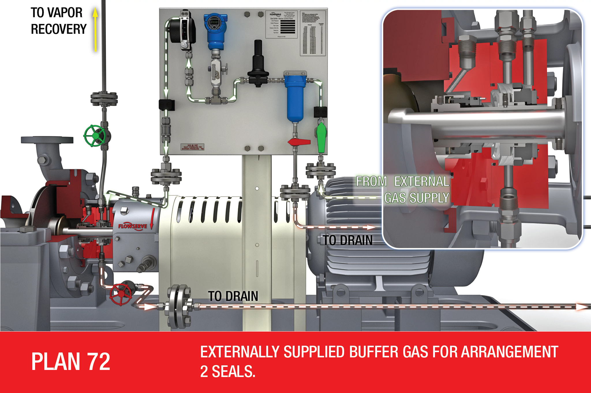
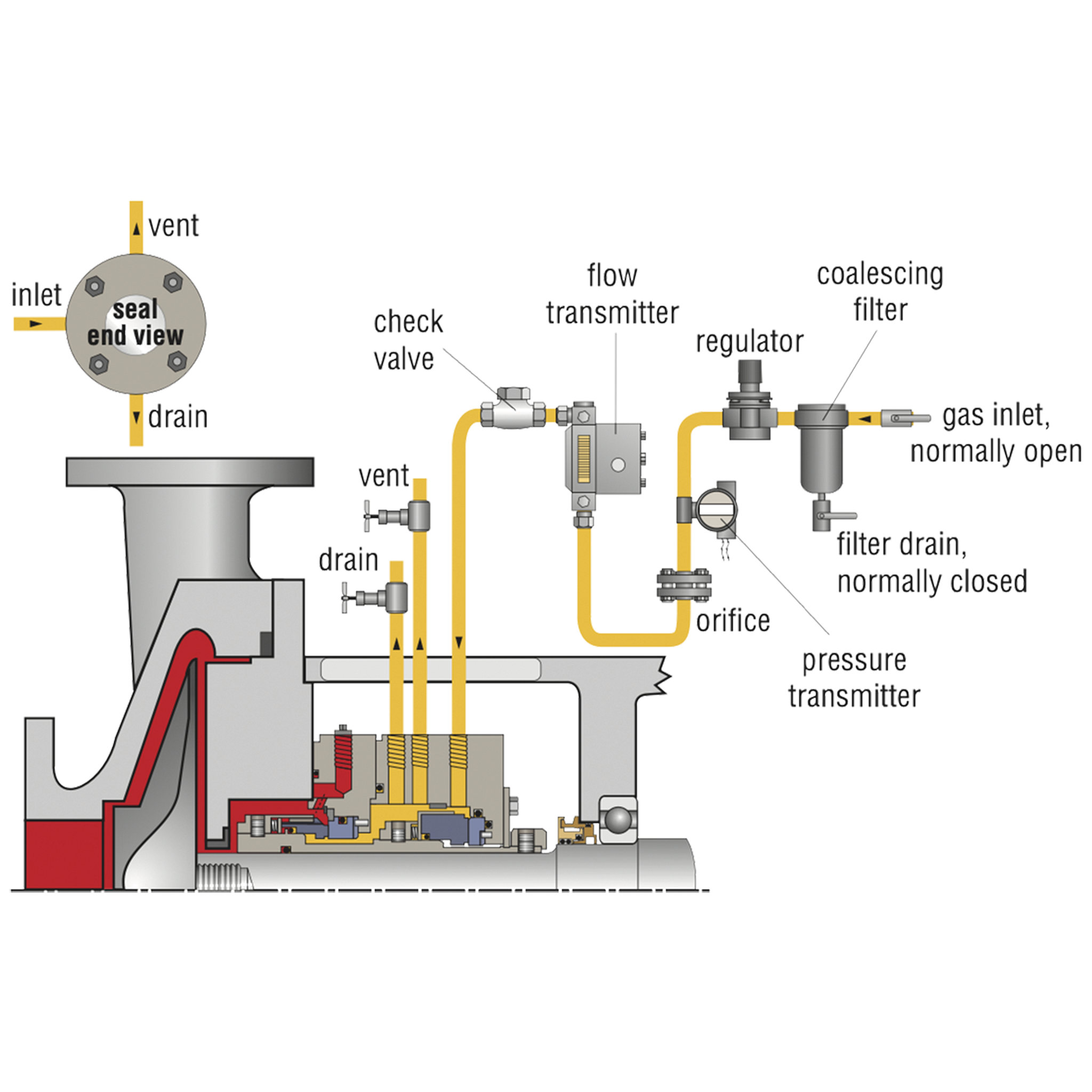
Plan 72
Externally supplied buffer gas for arrangement 2 seals.
What
Unpressurized buffer gas control system.
Containment seal support, typically with nitrogen buffer gas.
Why
Zero to very low process emissions.
Safety backup to primary seal.
Where
Used with dual unpressurized containment seals.
High vapor pressure fluids, light hydrocarbons.
Hazardous/toxic fluids.
Clean, non-polymerizing, non-oxidizing fluids.
Used in combination with Plan 75 and/or Plan 76.
Preventative Maintenance
Clean, reliable, low-pressure gas must be supplied to seal at all times.
Bottled gas supply is not recommended, except as part of emergency backup system.
Primary seal leakage is indicated by pressure in the vent line.
Vent or drain are usually connected to low-pressure vapor recovery/flare system.
Related Products
Plan 74
Externally supplied buffer gas for arrangement 3 seals.
What
Pressurized barrier gas control system.
Gas seal support, typically with nitrogen barrier gas.
Why
Isolate process fluid.
Zero process emissions.
Where
Used with dual pressurized gas seals.
High vapor pressure fluids, light hydrocarbons.
Hazardous/toxic fluids.
Services that do not tolerate liquid barrier seals.
Clean, non-polymerizing fluids.
Moderate-temperature fluids.
Preventative Maintenance
Clean, reliable, pressurized gas must be supplied to seal at all times.
Barrier pressure is typically at least 1.75 bar (25 psig) above seal chamber pressure.
Flow indicator shows both inboard and outboard seal leakage.
Bottled gas supply is not recommended, except as part of emergency backup system.
Related Products
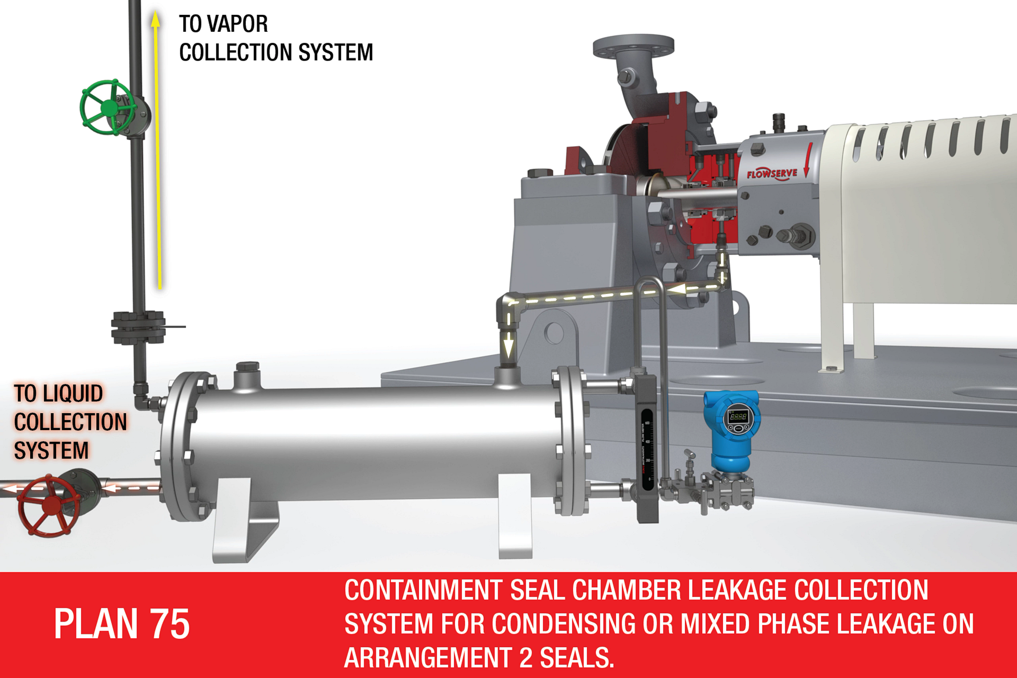
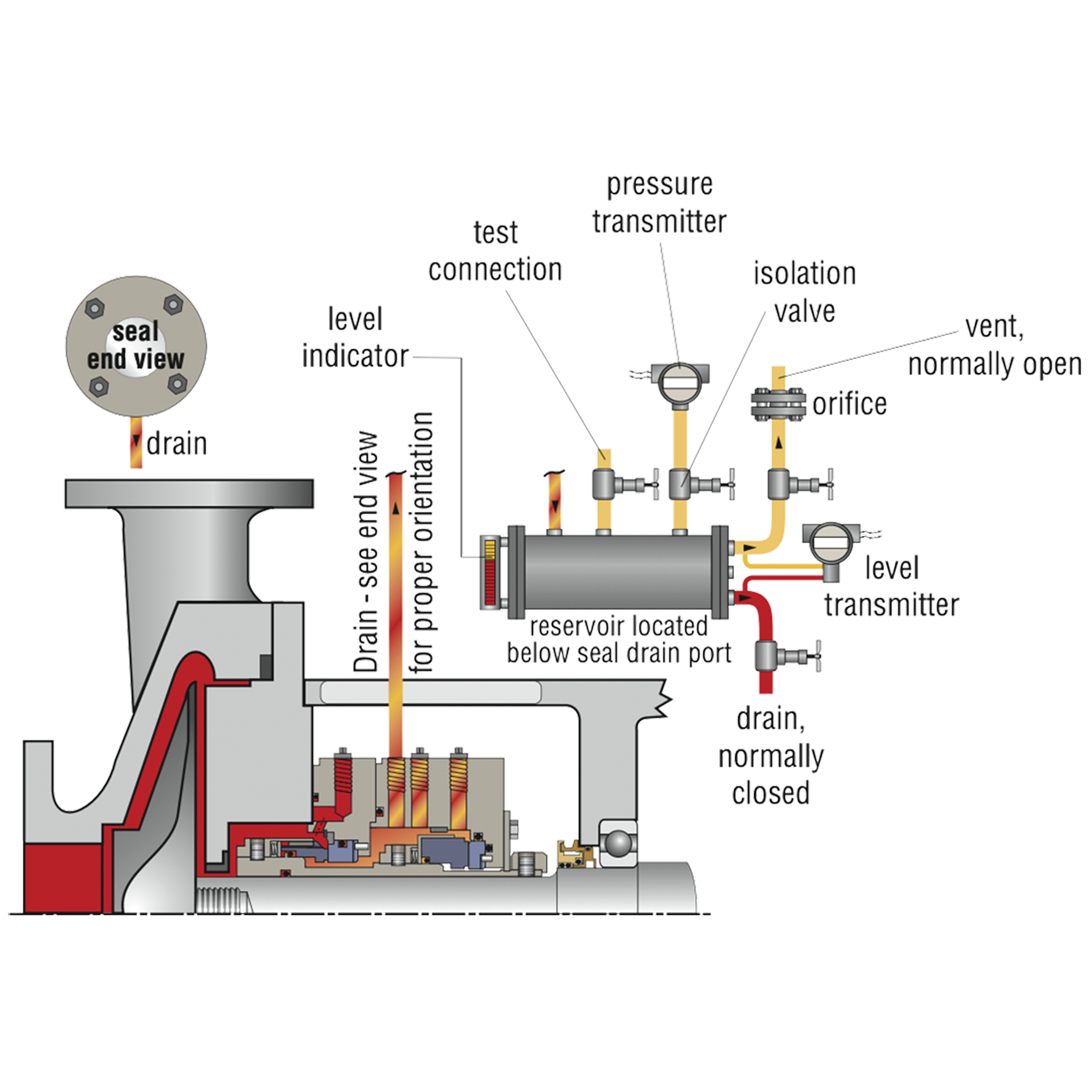
Plan 75
Containment seal chamber leakage collection system for condensing or mixed-phase leakage on arrangement 2 seals.
What
Drain from containment seal cavity to liquid collector and vapor recovery.
Why
Leakage collection for zero to very low process emissions.
Safety indicator for primary seal.
Where
May be used alone or with Plan 72 on containment seals.
Fluids that condense at ambient temperature.
High vapor pressure fluids, light hydrocarbons.
Hazardous/toxic fluids.
Clean, non-polymerizing, non-oxidizing fluids.
Preventative Maintenance
Collection reservoir must be located below seal drain and downward-sloped piping. Continuously vent collection reservoir to low-pressure vapor recovery/flare system. Drain collection reservoir to liquid recovery system as needed. Primary seal leakage is indicated by increased vent pressure. Monitor regularly for liquid level, valve settings and low vent pressure.
Plan 76
Containment seal chamber drain for non-condensing leakage on arrangement 2 seals.
What
Vent from containment seal cavity to vapor recovery.
Why
Leakage collection for zero to very low process emissions.
Safety indicator for primary seal.
Where
May be used alone or with Plan 72 on containment seals.
Fluids that do not condense at ambient temperature.
High vapor pressure fluids, light hydrocarbons.
Hazardous/toxic fluids.
Clean, non-polymerizing, non-oxidizing fluids.
Preventative Maintenance
Continuously vent to low-pressure vapor recovery/flare system.
Vent piping should include a condensate drain.
Primary seal leakage is indicated by increased vent pressure.
Monitor regularly for valve settings, blocked lines and low vent pressure.
Related Products
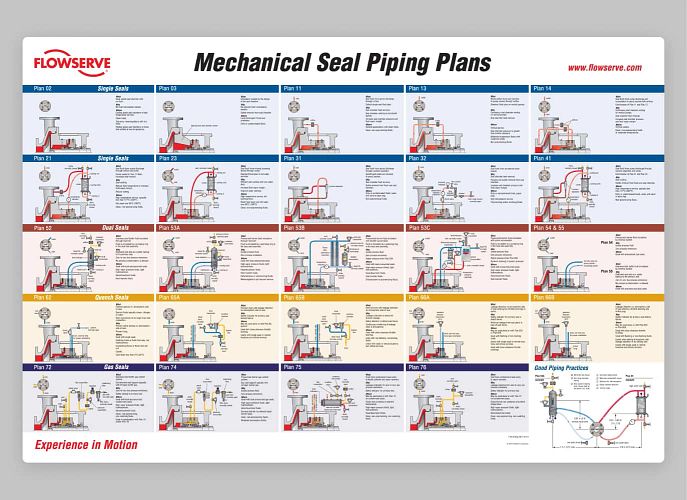
Flowserve Piping Plans Poster
See our mechanical seal piping plans, all in one convenient location.